-
E-mail
easson@aieasson.com
-
Phone
18358220577
-
Address
No. 10 Xincheng Road, Cicheng Town, Jiangbei District, Ningbo City, Zhejiang Province
Product Categories
Ningbo Yixin Optoelectronics Technology Co., Ltd
Gear module
NegotiableUpdate on 01/17
- Model
- Nature of the Manufacturer
- Producers
- Product Category
- Place of Origin
Overview
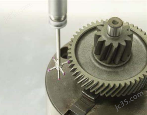
The Fato Inspect Gear gear analysis software package is based on CAD modeling and analysis technology. It can complete the modeling of the measured workpiece, tooth profile, helix, tooth pitch and other measured elements through the parameters or part models of gears and other workpieces. It also uses standard DMIS measurement programs to achieve measurement path planning and directly drives coordinate measuring machines to complete measurement data sampling. The software package can evaluate various error data and plot curves of measurement data according to international and domestic industry standards. The report format and content comply with industry standards and specifications, and can effectively support the production and manufacturing of complex parts in enterprises.
Product Details
lGear software Gear Module
Fato Inspect GearGear analysis software package based on CADModeling and analysis techniques can be used through gears, etcWorkpiece parametersor Complete the modeling of the measured workpiece, tooth profile, spiral line, tooth pitch and other measured elements in the part model, andAdopting standardsDMISMeasurement processImplement measurement path planning in sequence and directly drive coordinate measuring machines to complete measurement dataSampling. The software package can be customized according to international and domestic standardsEvaluate various error data and plot curves of measurement data using industry standards,The report format and content comply with industry standards and specifications, and can effectively support the production and manufacturing of complex parts for enterprises.
Coordinate system establishment

Gear measurement

Tooth pitch measurement


Tooth measurement


l Applicable range of gears The range of gears is applicableinvoluteGear module:Indescading gear module
Tooth profile of involute cylindrical external gear(tooth profile):Fα Theझील; F α Theƒha TheCαSpiral line(spiral)Fβ Theƒfβ TheƒHβ TheCβ
Tooth pitch(pitch): ƒptTheFpkTheSeaTheFP
Jumping in diameter(radial Run-out):Fr
Tooth profile of involute cylindrical internal gear(tooth profile):Fα Theझील; F α Theƒha TheCαSpiral line(spiral)Fβ Theƒfβ TheƒHβ TheCβ
Tooth pitch(pitch):ƒptTheFpkTheSeaTheFP
Jumping in diameter(radial Run-out):Fr
Involute external spline Gradually open the out-of-line flower keyInvolute internal spline Gradually open the inline flower key
Involute external thickening teeth Gradually open the outer thickening gear ofthe lineInvolute internally thickened gear Thicken the gears inside the gradually opening linerack The flank
Worm gear module:Worm worm module:
Linear(ZA TheZI TheZN)Worm gear tooth surface topology(profile topology):FcTooth pitch(pitch): ƒpt TheFpk TheSea TheFPJumping in diameter(radial Run-out):Fr
Linear(ZA TheZI TheZN)Worm gear profile(profile):Fc
End face, axial tooth pitch(pitch):ƒptTheFpk TheSea TheFPJumping in diameter(radial Run-out):Fr
ZK worm gearZK worm wheel
ZK worm ZK worm
ZC worm gear ZC worm wheel
ZC worm ZC worm
coneGear module:Cone gear module
The tooth profile of a spur bevel gear (tooth profile plate)(tooth profile):Fα Theझील; F α Theƒha
Tooth orientation(pitch trace):Fβ Theƒfβ TheƒHβ
toothDistance(pitch): ƒpt TheFpk TheSeaTheFP
Jumping in diameter(radial Run-out):Fr
Tooth surface topology of bevel gear (tooth surface topology version)(profile topology):Fc
toothDistance(pitch):ƒptTheFpkTheSeaTheFP
Jumping in diameter(radial Run-out):Fr
Straight cone tooth mold (tooth profile plate)) Straight tapered tooth mold(toothed profile version)
Straight cone tooth mold (tooth surface topology version)Straight tapered tooth mold (flank topology version)Helical bevel gear Oblique tooth cone gear
spiral bevel gear Spiral cone gearFace gear Face gear
Custom bevel gear Custom cone gear
Rectangular spline module:Rectangular Flower Key Module:Rectangular external spline Rectangular flower key
Rectangular internal spline The inner flower key of the rectangleRV Parts module:part module
Cycloidal external gear The outer gear of the swing line
Cycloidal internal gear The gears in the pendulumpin gear housing Needle shell
Screw outer rotor The outsideroil of the screwInternal rotor of screw The roil inside the screw
specialGear module:Special gear modules:
Linear external gear Straight toothed outer gear
Linear tooth enveloping gear Straight-toothedinner envelope gear
Measurement of involute cylindrical gears Cylindrical gear mapping outside the line
Measurement of involute internal cylindrical gears Cylindrical gear mapping within the gradually open lineThread (triangle, trapezoid)Threads(triangles,trapezoids)
Custom development for measuring complex parts Custom development of complex part measurements
l implementation method How it's implemented

1Open the software, enter the corresponding gear parameters, and generate IGSFormat Model
Open the software, enter each corresponding gear parameters, and generate Anigs formatmodel
2Three coordinate software import CADModel, establish coordinate system
The CAD model is imported into the three-coordinate software and the coordinate system is established
3Collect points on the left and right tooth surfaces of the first high gear, and input the actual coordinate values of the two points into the software X Y Z, left leaningAfter setting and right bias,X rotation angle , generate DIMS The program generates a new seat in the three coordinate software based on the calculated value after rotationStandard system
Starting to measure the first tooth high center left and right flanks respectively, the two actual
coordinate values into the software X Y Z, left bias and rightbias, X rotation angle, the generationof THES program, the value calculated after rotation in the three coordinate software to gPower Off new coordinate system
4Three coordinate software writing DIMSProgram, executionProgram measurement
The three-coordinate software writes to the SIMS program andperforms the programmeasurement
5Export coordinate point text in format, import into software to generate evaluation report
Export coordinate point text in format and import software to generate evaluation reports
l Introduction to Parameter Interface and Report Display
The parameter interface is described and presentedwith the report
(1)Parameter interface The parameter interface

Number of teeth: Enter the actual number of teeth of the workpiece.
Number of teeth:Enter the actual number of teeth for the work piece.
Modulus: Input the modulus of the workpiece.
Mods:Enter the modules ofthe work piece.
Tooth width: Enter the axial width of the workpiece.
Tooth width:Enter the width of the axial direction of the work piece.
Convert to coefficient: The input gear is converted to the quotient of the distance divided by the modulus during machining.
Change factor: The change distance divided by the modalitywhen entering gear machining.
Top diameter: Enter the tooth top height coefficient.
Topdiameter:Enterthe top height coefficient.
Root diameter: Enter the tooth root height coefficient.
Root diameter: Enter the root height coefficient.
Tooth types: divided into long teeth and short teeth, Long tooth crest height coefficient 1The short teeth are 0.8,Tooth tip outer diameter, Root diameter of teeth.
Tooth type: divided into long teeth and short teeth, long tooth top height coefficient 1, short toothis 0.8, tooth top outer diameter, root diameter.
Pressure angle: The tooth profile angle of the workpiece.
Pressure angle:The profile angle of the work piece.
Spiral angle: the angle between the helical surface of the workpiece along the tooth width direction and the axis
Spiral angle: The angle between the helix surface and the axis of the workman's teeth
Probe Name: According to RationalDMIS ,PCDMIS Format input in the program.
Head test name: According to rationalDMIS, PCDMIS program format to lose
Close range: the distance required for needle collection point detection.
Approximate distance: The distance required for pin detection.
Backward distance: The distance at which the measuring needle exits after picking up the point.
Fallback distance: Exit distance after pinpointing.
Measurement speed: Three coordinate execution DMIS Measurement speed during programming.
Measurement speed: The measurement speed at which three coordinates perform the DMISprogram.
Positioning speed: Three coordinate execution DMIS Positioning speed during programming.
speed: The positioning speed when the three coordinates execute the DMIS program.
Scanning speed: The three coordinate system is set when scanning the probe.
Scan speed: The three coordinates are set when the head is scanned.
Sampling density: The three coordinate system is set when scanning the probe.
Sample density: The three coordinates are set when the head is scanned.
Tooth tip safety distance: execution DMIS When changing teeth during programming, the distance between the measuring needle and the tooth tip should be reduced.
Top safety distance: The distance from the top of the tooth is regressed when the tooth change isperformed during the DMIS procedure.
Axial safety distance: execution DMISWhen the measuring head needs to change angle during programming, it should be positioned away from the upper end face of the gearDistance.
Pivot safety distance: The distance from the end face of the gear whenthe head needs to bechanged when performing the DMISprocedure.
BAngle (degree)):BAngle (degree)7.5When the measuring head needs to change angles,BThe angle needs to be rotated by the minimum angle.
B angle (degrees): B angle (degrees) 7.5, which means thatwhen the head needs to change theangle, the B angle needs to rotate the minimum angle.
AAngle (degree):In order to ensure that the measuring needle does not interfere during the measurement process,AThe angle must be set.
Angle A (degrees): In order to ensure that the needle does not interfere during the measurement, angle A must be setat an angle.
Measurement items: tooth profile, tooth direction, tooth pitch, according to measurement needsMake a selection.
items: profile, leading, pitch, select according to measurement needs.
Tooth surface: Select according to measurement needs, and when measuring tooth pitch, both left and right surfaces must be selected.
Flank: According to the measurement needs to be selected, the pitch measurement, the left and right sides must be selected.
Measuring tooth number: evenly distribute measurements as needed 1-16One tooth, also continuously measure some teeth.
Measuring the tooth number: Measure 1-16 teeth equally as needed, and also measure some teeth continuously.
Measurement position setting: Starting measurement, final measurement, starting evaluation, and final evaluation can be automatically calculated or manually entered.
Measurement location settings: start test, final test, evaluation, final evaluation can be calculatedautomatically, can also be entered manually.
Tooth profile pitch along tooth width height: refers to the measurement position of the tooth profile pitch along the tooth width height direction, which can be set, default is the middle of the tooth width.
Toothed d'aient section along the tooth width height: refers to the profiled persethalong the toothwidth height direction of the measuring position can be set,the default tooth width center.
Tooth pitch along tooth height extension:The measuring position along the tooth height and extension direction of the tooth circumferential pitchCan be set, default is the gear's indexing circle. The directional perseferity is extended along the tooth:the measuring position of the
tooth-to-the-week section along the long-term direction of the tooth spread can be set, and thedefault is the division circle of the gear.
Number of tooth profile measurement points: The number of tooth profile measurement points can be set as needed.
Profile points:The number of profile measurements can be set as needed.
Number of tooth alignment points: The number of tooth alignment measurement points can be set as needed.
Tooth points: The number of points for the tooth measurement can be set as needed.
(2)Report Display The report is displayed
tooth profile Profile:

tooth orientation lead:

tooth pitch pitch:


