-
E-mail
450660855@qq.com
-
Phone
13805846644
-
Address
No. 20 Xingxue Road, Yuyao City, Zhejiang Province
Ningbo Hengfeng CNC Machine Tool Co., Ltd
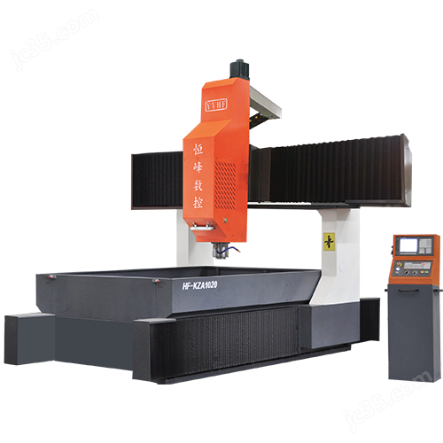
Mastering the correct usage method of the dynamic beam and column CNC gantry drilling machine is the key to ensuring machining quality
Date: 2025-12-01Read: 4
The dynamic beam and column CNC gantry drilling machine is a core equipment in the fields of heavy equipment manufacturing, ships, wind power, bridges, and large structural component processing. Its crossbeam and column can move longitudinally along the bed, and the spindle slider moves laterally and vertically on the crossbeam, achieving efficient and high-precision porous drilling of ultra large workpieces. Due to its large structure and complex movement, improper operation can easily lead to positioning deviation, tool breakage, guide rail wear, and even safety accidents. Mastering the correct usage method of the dynamic beam and column CNC gantry drilling machine is the key to ensuring machining quality and equipment lifespan.
1、 Preparation before startup
Cleaning of work area: Remove iron filings and debris from the bed track and T-shaped groove to ensure unobstructed movement of the crossbeam and column;
Stable clamping of workpieces: using specialized pressure plates, shim plates, and positioning pins to ensure that large workpieces do not shift or deform under drilling force; For thin plate workpieces, it is recommended to add support bars to prevent vibration;
Check the cooling and lubrication system: Confirm that the oil level of the automatic lubrication pump for the guide rail is normal, the coolant is sufficient, and there is no deterioration.
2、 Program import and empty run verification
CAM generates drilling program: Reasonably plan the cutting path to avoid excessive empty travel or emergency stop; Set a safe height (Z-axis lifting position) to prevent tool collision;
Simulation: Perform graphic simulation in the CNC system to check if the coordinate system and tool length compensation are correct;
Empty running test: Turn off the spindle rotation and only run each axis to confirm that there is no interference in the X/Y/Z/B (if any) linkage, especially paying attention to the synchronization between the moving beam and the moving column.
3、 Tool installation and parameter setting
Use qualified drill bits: Hard alloy or coated drill bits must have no broken edges and a runout of ≤ 0.02mm;
Accurate tool alignment: Using laser tool alignment or mechanical tool alignment to set the Z-axis zero point, ensuring consistent drilling depth;
Reasonable cutting parameters: Set the speed (n) and feed rate (f) according to the material (such as Q345 steel, stainless steel), for example, drilling carbon steel with a Φ 30mm drill bit: n ≈ 300rpm, f ≈ 0.2mm/rev, to avoid overloading and burning the tool.
4、 Monitoring and safety regulations during operation
Full on duty: No one is allowed to supervise, especially during the first hole processing stage;
Observe the chip removal status: Normally, it should be a spiral continuous iron chip. If there is powder or blockage, immediately pause and check if the cooling is sufficient or if the parameters are too extreme;
Do not manually intervene in moving parts: Do not touch the crossbeam, slider, or rotating spindle during operation.
5、 Shutdown and daily maintenance
First retreat the tool, then stop the machine: After completing the machining, the spindle returns to the reference point and the Z-axis rises to a safe height;
Cleaning iron filings and coolant: Use a magnetic chip remover or manually remove bed debris to prevent corrosion of the guide rail;
Apply anti rust oil: When the machine is stopped for a long time, apply anti rust grease to the exposed guide rails and screws.